
PRODUCTS
Butterfly Valve
Ball Valve
Gate Valve
Globe Valve
Check Valve
Marine valve
Forged Steel Valve
Others
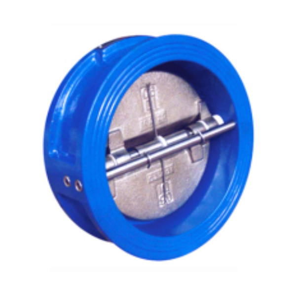
DIN Dual Plate Check Valve
Short Description
CharacteristicsExecutive standard Main parts material Body WCB(A105) ZG1Cr18Ni9Ti CFB(304) CF3(304L) ZG1Cr18Ni12Mo2Ti CF8M(316) CF3M(316M) Disc CF8 CF8 CF8 CF3 CF9M CF8M CF3M Stem 2Cr13 1Cr18Ni9Ti 0Cr18Ni9 00Cr19Ni10 ZG1Cr18Ni12Mo2Ti 0Cr17Ni12M..
Tags:Check Valve,Valve
 Print this page
  E-mail Us
 Bookmark This
 Skype Me
Quick Detail
Wafer dual plate check valve is used for pure pipelines and industrial, environmental, water treatment, high-rise building water supply and drainage pipelines to prevent reverse flow of medium. The check valve adopts a clip type, the disc has two semicircles, and the spring is forcibly reset, and the sealing surface can be a body wear welding wear material or a lining rubber, and the utility model has wide application range and reliable sealing.
Characteristics
1. Small size, light weight, compact structure and convenient maintenance
2. The valve plate adopts the dual type, which can be closed by itself under the elastic force of the spring.
3, due to the speed closure, can prevent the media from flowing backwards
4. The valve body structure has small length and good rigidity.
5, safe and convenient, can be used for horizontal and vertical installation
Executive standard
1, flange connection size: EN1092-1/ANSI B16.5/JIS B2220
2. Structure length: API 594, ISO 5752, EN 558.1/JIS B2002
Materials and main parameters
| Main parts material | Body | WCB(A105) | ZG1Cr18Ni9Ti | CFB(304) | CF3(304L) | ZG1Cr18Ni12Mo2Ti | CF8M(316) | CF3M(316M) |
| Disc | CF8 | CF8 | CF8 | CF3 | CF9M | CF8M | CF3M | |
| Stem | 2Cr13 | 1Cr18Ni9Ti | 0Cr18Ni9 | 00Cr19Ni10 | ZG1Cr18Ni12Mo2Ti | 0Cr17Ni12Mo2 | 00Cr17Ni14Mo2 | |
| Spring | 0Cr18Ni9 | 0Cr18Ni9 | 0Cr18Ni9 | 00Cr19Ni10 | 00Cr17Ni14Mo2 | 00Cr17Ni14Mo2 | 00Cr17Ni14Mo2 | |
| Applicable conditions | Applicable medium | Water, steam, oil, etc. | Corrosive medium such as nitric acid | Strong oxidizing medium | Corrosive medium such as nitric acid | Corrosive medium such as urea | ||
| Temperature(℃) | -29~425 | -196~540 | -196~425 | -196~540 | -196~455 | |||
| Note: This table is the model of the conventional wafer type check valve, the main parts and materials and applicable working conditions. For other requirements and model preparation, please refer to the model of the clamp type check valve. |
||||||||
Main size and weight
| PNMPa | DNmm | Dimension(mm) | Wet. (Kg) |
Piping flange (for reference) | ||||||
|---|---|---|---|---|---|---|---|---|---|---|
| L | D | D3 | D2 |
Bolt hole center diam D1 |
Bolt Quantity |
Bolt diam d |
Bolt length Ll |
|||
| PN1.0MPa | 50 | 43 | 108 | 56 | 51 | 2 | 125 | 4 | M16 | 150 |
| 65 | 46 | 128 | 73 | 65 | 3 | 145 | 4 | M16 | 155 | |
| 80 | 64 | 142 | 88 | 80 | 4 | 160 | 8 | M16 | 160 | |
| 100 | 64 | 162 | 108 | 102 | 6 | 180 | 8 | M16 | 165 | |
| 125 | 70 | 192 | 132 | 127 | 8 | 210 | 8 | M16 | 180 | |
| 150 | 76 | 218 | 160 | 152 | 13 | 240 | 8 | M20 | 205 | |
| 200 | 89 | 273 | 210 | 203 | 24 | 295 | 8 | M20 | 235 | |
| 250 | 114 | 328 | 266 | 254 | 37 | 350 | 12 | M20 | 255 | |
| 300 | 114 | 378 | 310 | 305 | 50 | 400 | 12 | M20 | 290 | |
| 350 | 127 | 438 | 355 | 350 | 76 | 460 | 16 | M20 | 295 | |
| 400 | 140 | 489 | 405 | 400 | 110 | 515 | 16 | M24 | 310 | |
| 450 | 152 | 539 | 455 | 450 | 135 | 565 | 20 | M24 | 325 | |
| 500 | 152 | 594 | 505 | 500 | 158 | 620 | 20 | M24 | 345 | |
| 600 | 178 | 696 | 605 | 600 | 320 | 725 | 20 | M27 | 355 | |
| 700 | 229 | 811 | 700 | 675 | 380 | 840 | 24 | M27 | 440 | |
| 800 | 241 | 918 | 800 | 796 | 560 | 950 | 24 | M30 | 450 | |
| 900 | 241 | 1018 | 903 | 898 | 640 | 1050 | 28 | M30 | 520 | |
| 1000 | 300 | 1124 | 1055 | 1050 | 900 | 1160 | 28 | M33 | 590 | |
| 1200 | 350 | 1340 | 1205 | 1200 | 1400 | 1380 | 32 | M36 | 695 | |
| PN1.6MPa | 50 | 43 | 108 | 56 | 51 | 2 | 125 | 4 | M16 | 150 |
| 65 | 46 | 128 | 73 | 65 | 3 | 145 | 4 | M16 | 155 | |
| 80 | 64 | 142 | 88 | 80 | 4 | 160 | 8 | M16 | 160 | |
| PN MPa | DNmm | Dimension(mm) |
Wet. (Kg) |
Piping flange (for reference) | ||||||
|---|---|---|---|---|---|---|---|---|---|---|
| L | D | D3 | D2 |
Bolt hole center diam D1 |
Bolt Quantity |
Bolt diam d |
Bolt length Ll |
|||
| PN1.6MPa | 100 | 64 | 162 | 108 | 102 | 6 | 180 | 8 | M16 | 165 |
| 125 | 70 | 192 | 132 | 127 | 8 | 210 | 8 | M16 | 180 | |
| 150 | 76 | 218 | 160 | 152 | 13 | 240 | 8 | M20 | 205 | |
| 200 | 89 | 273 | 210 | 203 | 24 | 295 | 12 | M20 | 235 | |
| 250 | 114 | 329 | 266 | 254 | 39 | 355 | 12 | M24 | 265 | |
| 300 | 114 | 384 | 310 | 305 | 50 | 410 | 12 | M24 | 305 | |
| 350 | 127 | 444 | 355 | 350 | 76 | 470 | 16 | M24 | 310 | |
| 400 | 140 | 496 | 405 | 400 | 110 | 525 | 16 | M27 | 330 | |
| 450 | 152 | 556 | 455 | 450 | 135 | 585 | 20 | M27 | 345 | |
| 500 | 152 | 618 | 505 | 500 | 158 | 650 | 20 | M30 | 370 | |
| 600 | 178 | 732 | 605 | 600 | 320 | 770 | 20 | M33 | 380 | |
| 700 | 229 | 802 | 700 | 695 | 380 | 840 | 24 | M33 | 470 | |
| 800 | 241 | 912 | 800 | 796 | 560 | 950 | 24 | M36 | 475 | |
| 900 | 241 | 1012 | 903 | 898 | 640 | 1050 | 28 | M36 | 545 | |
| 1000 | 300 | 1126 | 1055 | 1050 | 900 | 1170 | 28 | M39 | 620 | |
| 1200 | 350 | 1340 | 1205 | 1200 | 1400 | 1390 | 32 | M45 | 735 | |
| PN2.5MPa | 50 | 60 | 108 | 56 | 51 | 2 | 125 | 4 | M16 | 150 |
| 65 | 67 | 128 | 73 | 65 | 3 | 145 | 8 | M16 | 160 | |
| 80 | 73 | 142 | 88 | 80 | 4 | 160 | 8 | M16 | 170 | |
| 100 | 73 | 168 | 108 | 102 | 6 | 190 | 8 | M20 | 180 | |
| 125 | 86 | 194 | 132 | 127 | 8 | 220 | 8 | M24 | 205 | |
| 150 | 98 | 224 | 160 | 152 | 14 | 250 | 8 | M24 | 220 | |
| 200 | 127 | 284 | 210 | 203 | 27 | 310 | 12 | M24 | 255 | |
| 250 | 146 | 341 | 266 | 254 | 42 | 370 | 12 | M27 | 285 | |
| 300 | 181 | 401 | 310 | 305 | 54 | 430 | 16 | M27 | 325 | |
| 350 | 184 | 458 | 355 | 350 | 86 | 490 | 16 | M30 | 340 | |
| 400 | 191 | 515 | 405 | 40 | 120 | 550 | 16 | M33 | 360 | |
| 450 | 203 | 565 | 455 | 450 | 148 | 600 | 20 | M33 | 375 | |
| 500 | 219 | 622 | 505 | 500 | 165 | 660 | 20 | M33 | 395 | |
| 600 | 222 | 732 | 605 | 600 | 340 | 770 | 20 | M36 | 410 | |
| 700 | 305 | 831 | 700 | 695 | 400 | 875 | 24 | M39 | 500 | |
| 800 | 305 | 942 | 800 | 796 | 580 | 990 | 24 | M45 | 520 | |
| 900 | 368 | 1040 | 903 | 898 | 660 | 1090 | 28 | M45 | 590 | |
| 1000 | 432 | 1155 | 1055 | 1050 | 960 | 1210 | 28 | M52 | 675 | |
| 1200 | 524 | 1365 | 1205 | 1200 | 1440 | 1420 | 32 | M52 | 790 | |
| PN MPa | DN mm | Dimension(mm) |
Wet. (Kg) |
Piping flange (for reference) | |||||||
|---|---|---|---|---|---|---|---|---|---|---|---|
| L | D | D3 | D2 |
Bolt hole center diam D1 |
Bolt Quantity |
Bolt diam d |
Bolt length L1 |
||||
| RF、MFM | RJ | ||||||||||
| PN4.0MPa | 50 | 60 | 108 | 58 | 51 | 3 | 125 | 4 | M16 | 150 | - |
| 65 | 67 | 125 | 73 | 65 | 4 | 145 | 8 | M16 | 160 | - | |
| 80 | 73 | 142 | 88 | 80 | 6 | 160 | 8 | M16 | 170 | - | |
| 100 | 73 | 168 | 108 | 102 | 8 | 190 | 8 | M20 | 180 | - | |
| 125 | 86 | 194 | 132 | 127 | 13 | 220 | 8 | M24 | 205 | - | |
| 150 | 98 | 224 | 160 | 152 | 16 | 250 | 8 | M24 | 220 | - | |
| 200 | 127 | 291 | 210 | 203 | 28 | 320 | 12 | M27 | 270 | - | |
| 250 | 146 | 353 | 266 | 254 | 49 | 385 | 12 | M30 | 300 | - | |
| 300 | 181 | 418 | 310 | 305 | 76 | 450 | 16 | M30 | 3485 | - | |
| 350 | 222 | 475 | 355 | 350 | 114 | 510 | 16 | M33 | 400 | - | |
| 400 | 232 | 547 | 405 | 400 | 190 | 585 | 16 | M36 | 425 | - | |
| 450 | 264 | 572 | 455 | 450 | 200 | 610 | 20 | M36 | 470 | - | |
| 500 | 292 | 626 | 505 | 500 | 260 | 670 | 20 | M39 | 505 | - | |
| 600 | 318 | 745 | 608 | 600 | 404 | 795 | 20 | M45 | 575 | - | |
| PN6.3MPa | 50 | 60 | 114 | 58 | 51 | 4 | 135 | 4 | M20 | 170 | 185 |
| 65 | 67 | 138 | 73 | 65 | 5 | 160 | 8 | M20 | 180 | 195 | |
| 80 | 73 | 148 | 88 | 80 | 7 | 170 | 8 | M20 | 190 | 205 | |
| 100 | 79 | 174 | 108 | 102 | 10 | 200 | 8 | M24 | 210 | 225 | |
| 125 | 105 | 221 | 132 | 127 | 16 | 240 | 8 | M27 | 250 | 265 | |
| 150 | 136 | 248 | 162 | 152 | 20 | 280 | 8 | M30 | 290 | 305 | |
| 200 | 165 | 310 | 212 | 200 | 38 | 345 | 12 | M33 | 335 | 350 | |
| 250 | 213 | 362 | 266 | 250 | 62 | 400 | 12 | M33 | 395 | 410 | |
| 300 | 229 | 422 | 310 | 305 | 100 | 460 | 16 | M33 | 420 | 435 | |
| 350 | 273 | 487 | 355 | 350 | 160 | 525 | 16 | M36 | 480 | 495 | |
| 400 | 305 | 541 | 405 | 400 | 260 | 585 | 16 | M39 | 525 | 540 | |
| PN10.0MPa | 50 | 60 | 120 | 58 | 51 | 5 | 145 | 4 | M24 | 185 | 200 |
| 65 | 67 | 144 | 73 | 65 | 7 | 170 | 8 | M24 | 195 | 210 | |
| 80 | 73 | 154 | 88 | 80 | 10 | 180 | 8 | M24 | 205 | 220 | |
| 100 | 79 | 181 | 108 | 102 | 12 | 210 | 8 | M27 | 225 | 240 | |
| 125 | 105 | 218 | 132 | 127 | 19 | 250 | 8 | M30 | 265 | 280 | |
| 150 | 136 | 258 | 162 | 152 | 25 | 290 | 12 | M30 | 305 | 320 | |
| 200 | 165 | 324 | 212 | 200 | 56 | 360 | 12 | M33 | 355 | 370 | |
| 250 | 213 | 392 | 266 | 250 | 94 | 430 | 12 | M36 | 425 | 440 | |
| 300 | 229 | 456 | 312 | 305 | 142 | 500 | 16 | M39 | 465 | 480 | |
| 350 | 273 | 510 | 355 | 350 | 230 | 560 | 16 | M45 | 535 | 550 | |
| 400 | 305 | 570 | 405 | 400 | 366 | 620 | 16 | M45 | 585 | 600 | |
| PN MPa | DN mm | Dimension(mm) |
Wet. (Kg) |
Piping flange (for reference) | |||||||
|---|---|---|---|---|---|---|---|---|---|---|---|
| L | D | D3 | D2 |
Bolt hole center diam D1 |
Bolt Quantity |
Bolt diam d |
Bolt length Ll |
||||
| RF、MFM | RJ | ||||||||||
| PN16.0MPa |
50 | 70 | 120 | 56 | 51 | 7 | 145 | 4 | M24 | 210 | 225 |
| 65 | 83 | 144 | 73 | 65 | 10 | 170 | 8 | M24 | 235 | 250 | |
| 80 | 83 | 154 | 90 | 80 | 14 | 180 | 8 | M24 | 245 | 260 | |
| 100 | 102 | 181 | 108 | 102 | 17 | 210 | 8 | M27 | 280 | 295 | |
| 125 | 110 | 218 | 136 | 127 | 28 | 250 | 8 | M30 | 305 | 320 | |
| 150 | 159 | 258 | 162 | 152 | 36 | 290 | 12 | M30 | 365 | 385 | |
| 200 | 206 | 325 | 212 | 203 | 78 | 360 | 12 | M33 | 425 | 445 | |
| 250 | 241 | 389 | 266 | 254 | 130 | 430 | 12 | M39 | 495 | 515 | |
| 300 | 292 | 459 | 312 | 305 | 210 | 500 | 16 | M39 | 570 | 600 | |
| PN20.0MPa |
50 | 70 | 136 | 56 | 51 | 8 | 160 | 8 | M22 | 215 | 230 |
| 65 | 83 | 174 | 73 | 65 | 16 | 203 | 8 | M27 | 255 | 270 | |
| 80 | 83 | 198 | 90 | 80 | 22 | 230 | 8 | M30 | 270 | 285 | |
| 100 | 102 | 254 | 108 | 102 | 35 | 292 | 8 | M36 | 330 | 345 | |
| 125 | 110 | 280 | 136 | 127 | 50 | 318 | 12 | M36 | 355 | 375 | |
| 150 | 159 | 316 | 162 | 152 | 78 | 360 | 12 | M42 | 430 | 450 | |
| 200 | 206 | 390 | 212 | 203 | 120 | 440 | 12 | M48 | 510 | 530 | |
| 250 | 248 | 518 | 266 | 254 | 220 | 572 | 16 | M52 | 595 | 625 | |
| PN25.0MPa |
50 | 70 | 124 | 56 | 51 | 8 | 150 | 8 | M24 | 215 | 230 |
| 65 | 83 | 154 | 73 | 65 | 14 | 180 | 8 | M24 | 235 | 250 | |
| 80 | 83 | 171 | 90 | 80 | 20 | 200 | 8 | M27 | 250 | 265 | |
| 100 | 102 | 203 | 108 | 102 | 28 | 235 | 8 | M30 | 290 | 305 | |
| 125 | 10 | 243 | 136 | 127 | 44 | 275 | 12 | M30 | 310 | 325 | |
| 150 | 159 | 285 | 162 | 152 | 70 | 320 | 12 | M33 | 385 | 405 | |
| 200 | 206 | 359 | 212 | 203 | 110 | 400 | 12 | M39 | 470 | 490 | |
| 250 | 248 | 443 | 266 | 254 | 200 | 490 | 16 | M45 | 560 | 580 | |
| 300 | 305 | 540 | 312 | 305 | 350 | 590 | 16 | M48 | 665 | 695 | |